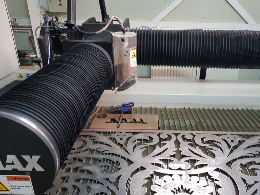
Bellows used on OnMax Water jet Cutter
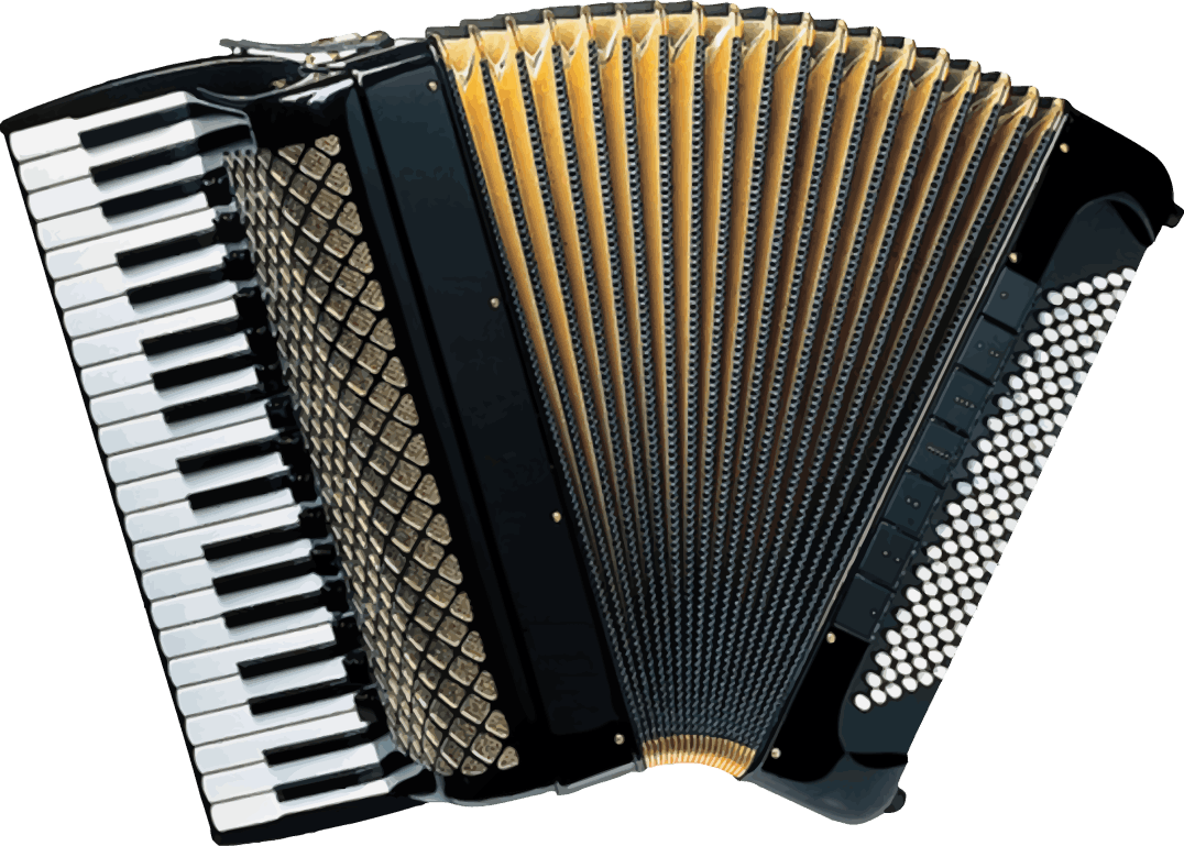
Bass Piano Accordion As Air Collector
Objectives
Individual Assignment
1) Design and produce something with a digital fabrication process (incorporating computer-aided design and manufacturing) not covered in another assignment, documenting the requirements that your assignment meets, and including everything necessary to reproduce it.
Bellows used on OnMax Water jet Cutter
Bass Piano Accordion As Air Collector

Long Story Short
Specifications: Repeatability +/- 0.03 mm, position accuracy +/- 0.1 mm/m, working area 1800 mm x 2500 mm, high speed router 3.6kW 50,000 rpm
Applications: A range of modules provide the capability to cut, score, crease and mill. Use cases include origami/kirigami for rapid cutting-and-folding of structures with tunable properties, two sided milling for press fit furniture and cutting of carbon fiber, fabric for composite lay ups.
The ZUND is modular cutting system that can be adapted and used to cut, route and draw on a range of materials. With interchangeable modules, tools and blades, the ZUND can be configured to cut vinyl, fabric, leather, cardboard, foam core, rubber and many more!
Software requirement
Cutter editor, Cut queue, Cut center, Cut Manager
Tools:
There are several different types of tools that can be used with the Zund Cutting System.
Cutting
1. Electric Oscillating Tool – EOT
2. Power Rotary Tool – PRT
3. Electric Oscillating Tool – EOT-250
4. Driven Rotary Tool – DRT
5. Pneumatic Oscillating Tool – POT
6. Wheel Knife Tool – WKT
7. Universal Cutting Tool – UCT
8. Passepartout Tool – PPT
9. Scoring Cutting Tool – SCT
10. Laser Module – LM 100W
11. V-Cut Tool – VCT
Kiss-Cutting
1. Kiss-Cut Module – KCM-S
2. Kiss-Cut Tool – KCT
Creasing
1. Creasing Tool Type 1 – CTT1
2. Creasing Tool Type 2 – CTT2
3. Creasing Tool Type 3 – CTT3
Perforating
1. Perforating Tool Type 1 – PTT1
Routing & engraving
1. Universal Routing Tool – URT
2. Automatic Router Bit Changer – ARC
Punching
1. Punch Modules – PUM
Marking & plotting
1. Marker Modules – MAM
2. Universal Drawing Tool – UDT
3. Raster Braille Tool – RBT
For manual please refer this link.(Warning.PDF)
To know detail about each tool please follow this link.
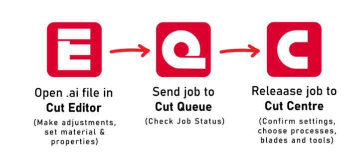
For workflow please refer this link.
For tutorial please follow this link.
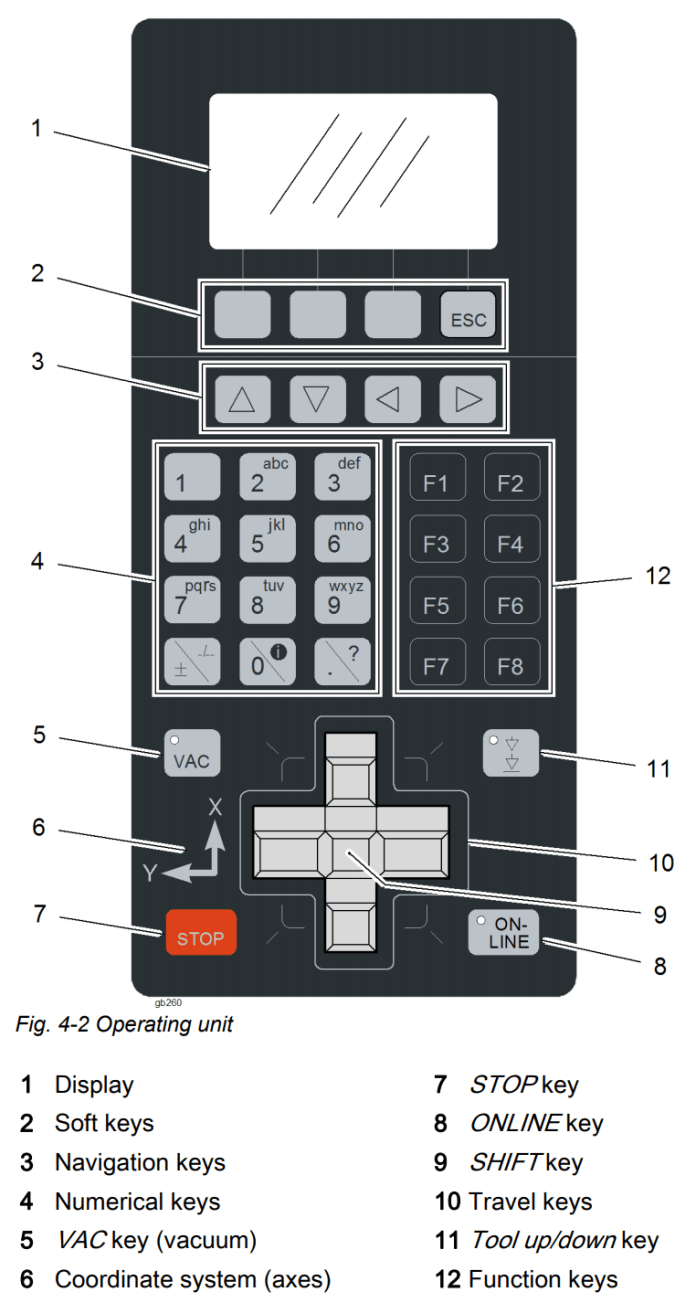
The console directly controls the cutter without going through the software. The console is used primarily for performing tool changes, turning the machine on/off and switching between online and offline mode. The gantry can be manually controlled by the travel keys and moved rapidly by holding the 'shift' key.
The Vacuum can be toggled on and off by pressing the 'shift' key and 'VAC' key. Pressing any of the travel keys of 'STOP' during a cutting operation will pause the job and raise the tool until the 'Online' button is pressed, resuming the job.
Light Barriers & Emergency Stop
The Zund has safety features to prevent injury during operation. The main feature is a series of 'light barriers' that are projected from one end of the gantry to the other on the front and back side of the cutter. If these beams are broken by someone reaching into the operating area, or if a piece of stock lifts up unexpectedly, the cutter will immediately stop operation. To continue the operation after everything is cleared from the table, press 'OK' then 'Online' to continue the cut from where it stopped.
While the light barriers are a soft stop, the red emergency stop buttons are a hard stop. When the emergency stop is pressed the operation immediately stops, cancels the current job and disengages the tools. To continue from an emergency stop the button must be twisted to be released, then follow the instructions on screen. The tools will re-engage and require initialisation and the job will need to be restarted from the PC.
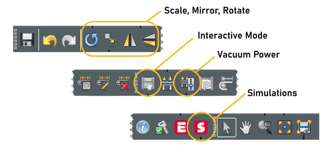
Rotate, Scale, Offset and Mirror - allows adjustments to the objects before cutting
Interactive Mode - Zund must be 'online' to activate interactive mode. Can control placement of cutters and set reference points from computer.
Vacuum Power - Adjusts vacuum strength and can turn vacuum on/off.
Simulations - Starts a simulation of job before it cuts/draws. Used to check material placement and ensure tool paths are correct
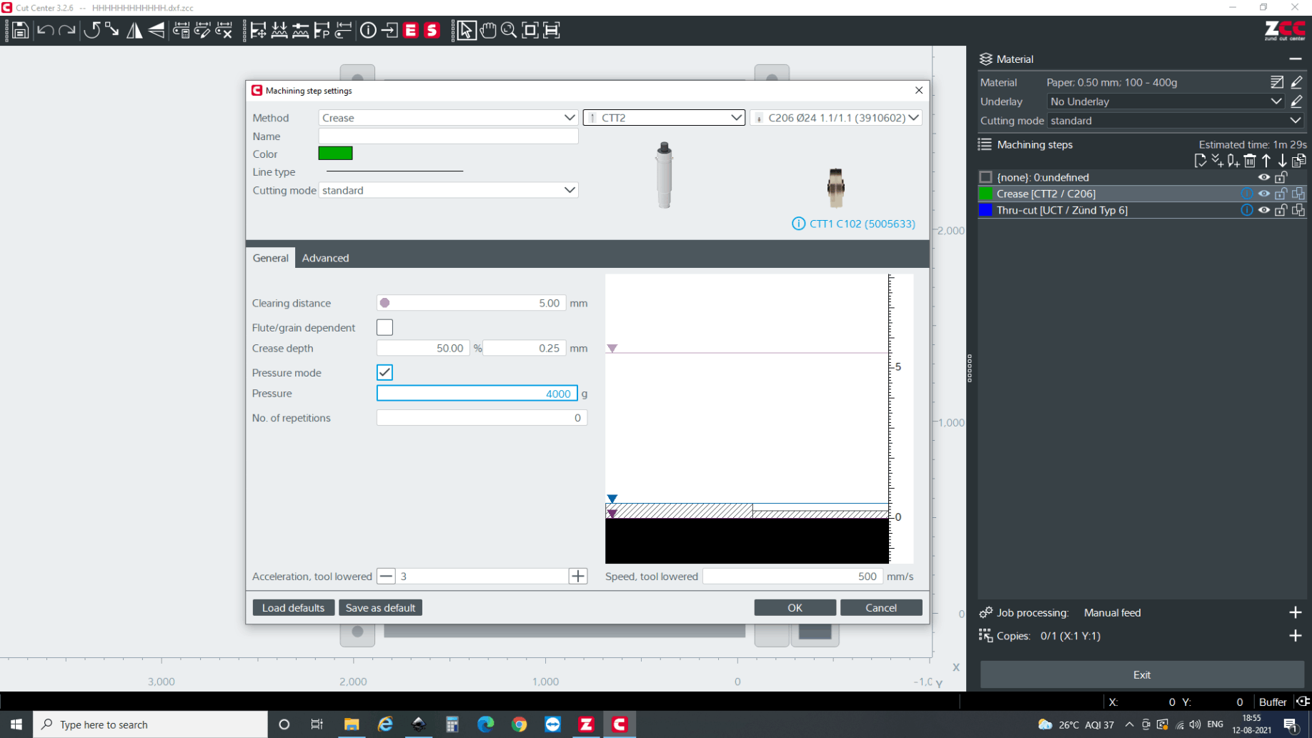
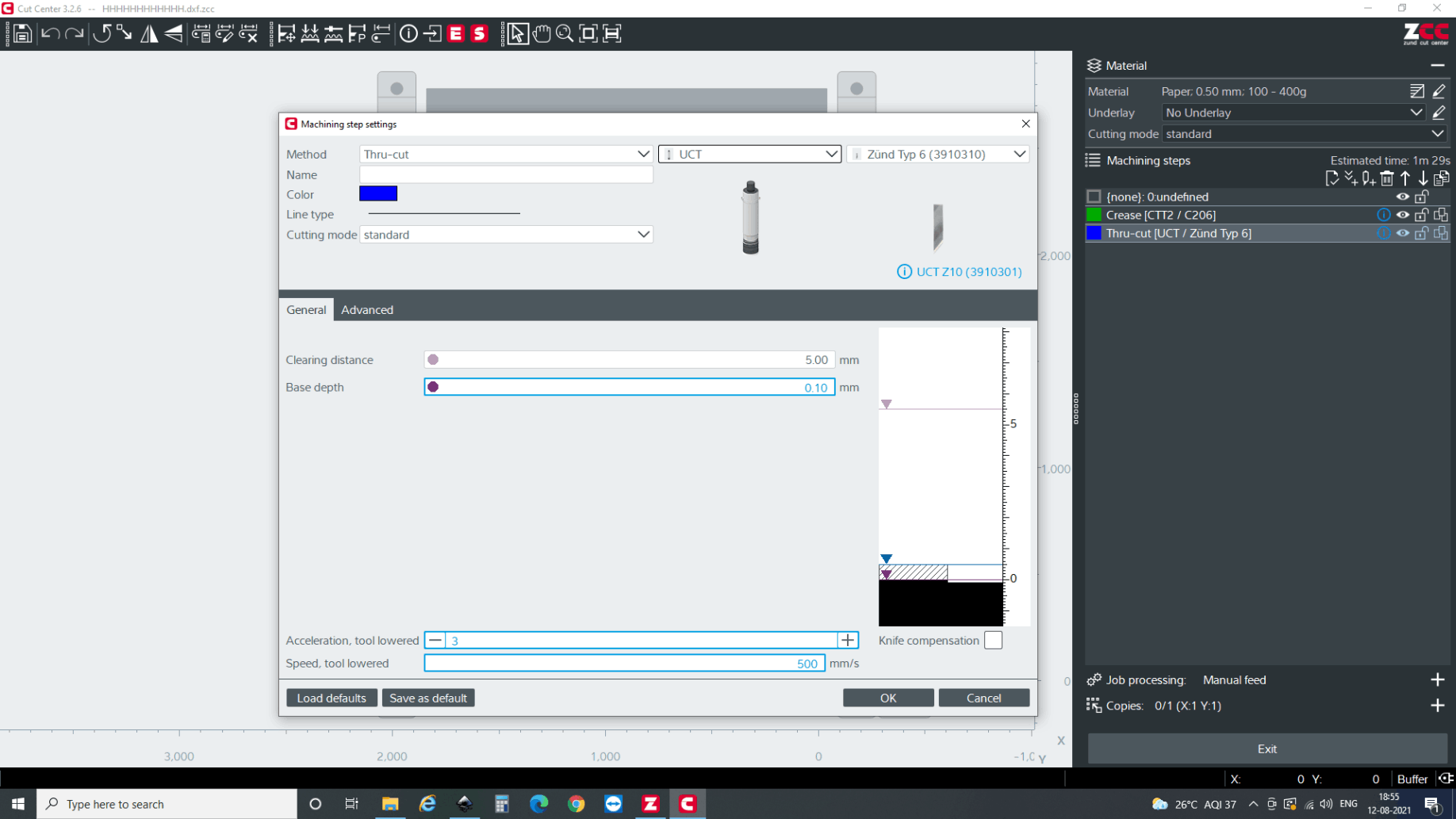
1. Method: The type of operation to be performed. Each material has a set of available operations depending on its characteristics.
2. Name: What the layer will appear as on the right hand side of the screen.
Color: The color the layer will render as on the screen.
3. Line type: Whether the operation will perform along a solid, dotted, or dashed line.
4. Cutting mode: Always set to standard.
5. Tool selection: Drop down menu will allow the selection of the tool to be used during the operation, if multiple are allowed.
6. Tool insert selection: Select the tool insert (blade or bit) to be used during the operation.
7. Initialization: Where the tool will register height from. Alway set to base.
8. Clearing distance: How high above the top of the material the tool will retract to travel. Does not need to be adjusted from default.
9. Material thickness: Current thickness of the material. Cannot be altered through this window, needs to be set in the material selection window.
10. Base depth: How deep relative to the table the material will cut. Should never be more than +/-.005. Adjust in small increments (+/-.002) if blade is not cutting all the way through the stock.
11. Multi. pass max. depth: The most stepdown the router will perform on a single layer. Should not exceed .0500in.
12. Multi. pass last depth: The depth of the final routing layer. If using bridges, should be at least .0200in, as bridges are formed from this layer.
13. Machining depth: The specified depth for engraving operations.
14. Score depth: The specified depth of a score, either in inches or percentage of material thickness.
15. Acceleration, tool lowered: The maximum acceleration the tool will travel while cutting the material, from 1-4.
Speed, tool lowered: The maximum speed the tool will travel while cutting the material. Slow down for a cleaner cut in most materials.
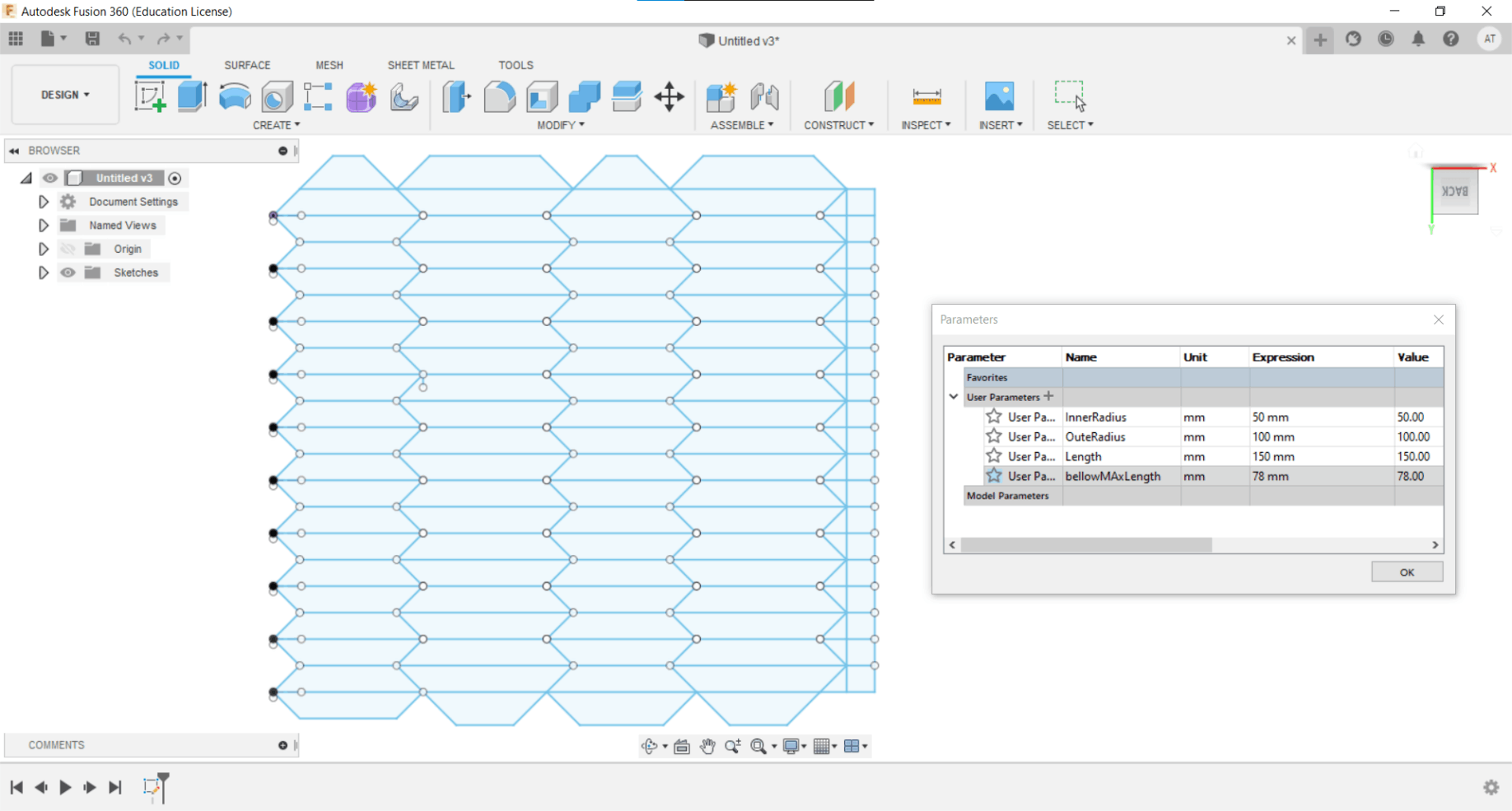
So I opened up Fusion 360 And Sketched the Bellow 2D(Thanks Array And Mirror Feature) cut file With parameters A Length of bellow,Inner radius and Outer radius.The outer portion is to cut and all inner regions should be Creased. drawing is made and the DXF file is exported for fabrication
the dxf file is exported on 1:1 scale from the CAD software, It is imported in the software that zund has, i.e cut editor.
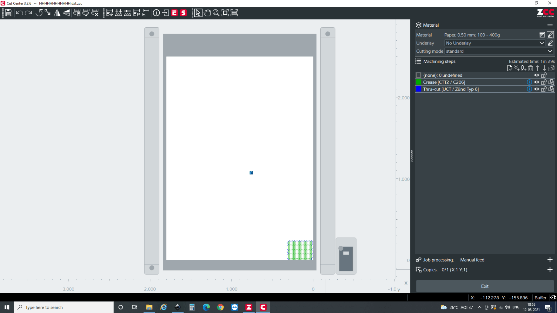
Cut Editor with Imported .dxf file
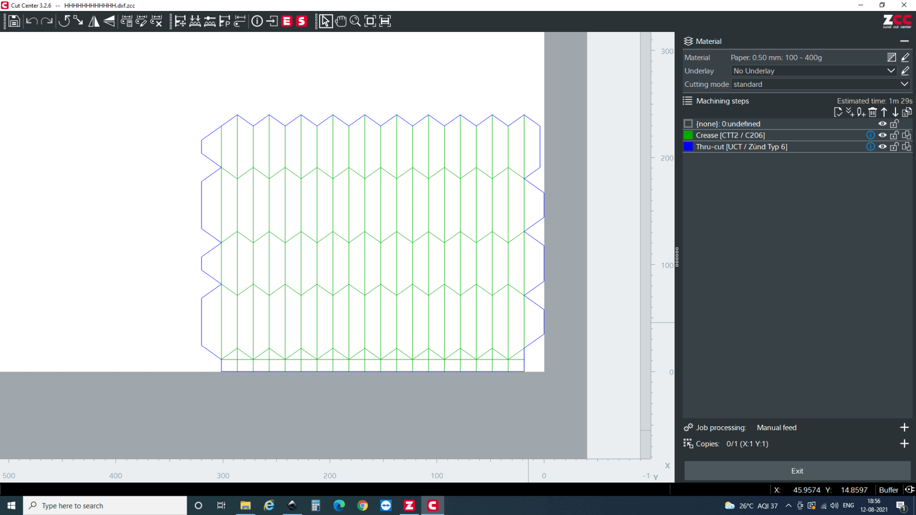
There are two main attributes for the part. i.e through cut and crease. So, first, I selected lines which is to be creased. Then after the lines are selected, you can right click , select change method >> new method and select method attributes. Here, you will have a multiple options but I need crease for now so selected crease.
Make sure that the operation is in order meaning that first it should be register, crease and then cut.
Select the tools.
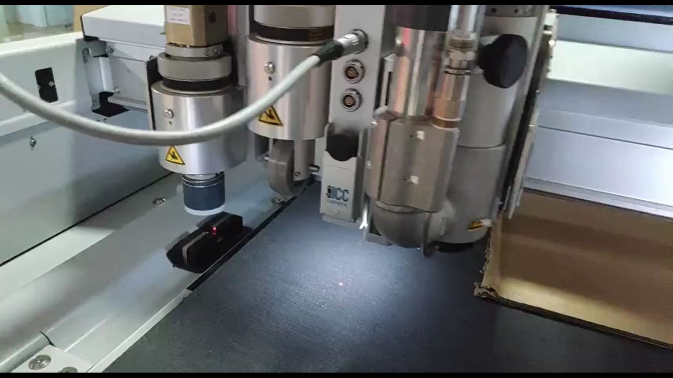
Then you again have to register the home position for X and Y axis. Then it automatically sets up the Z position by different process. For creasing, the creasing wheel is pushed against the datum and force is taken as a reference to set up Z height. How ever for the oscillating tool, the tool is reciprocated in the above laser until it crosses the laser detecting the Z-0 height.
Cutting And creasing In super fast
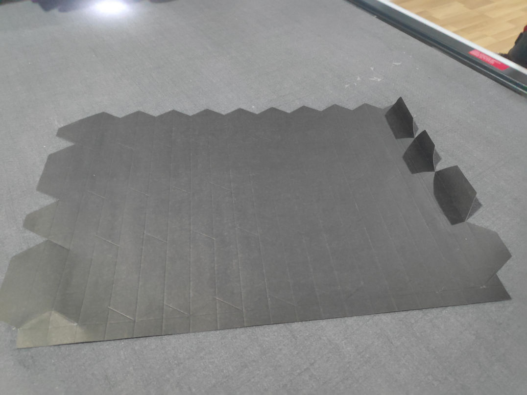
Successfully done on chart paper
Frist Trail.
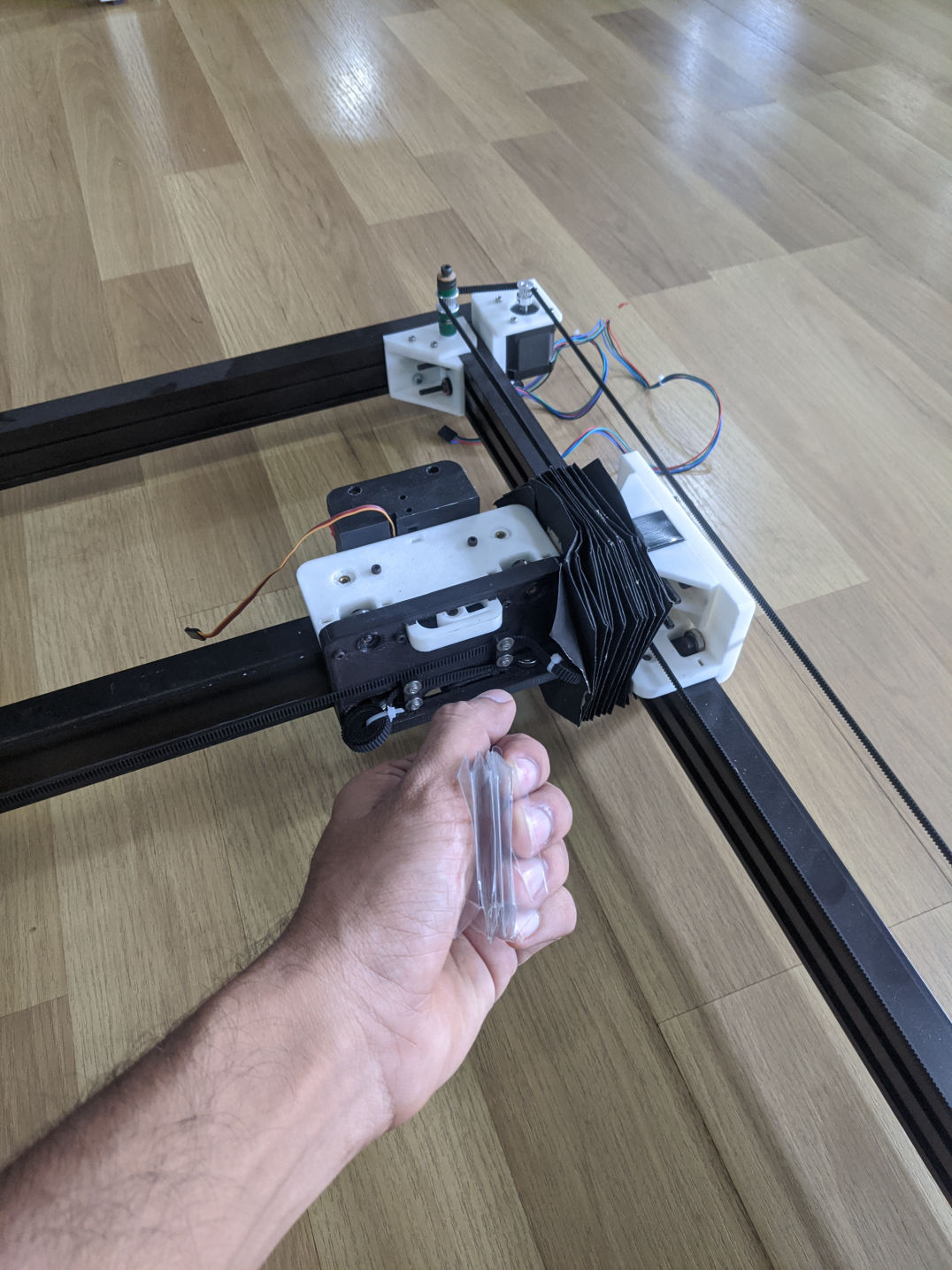
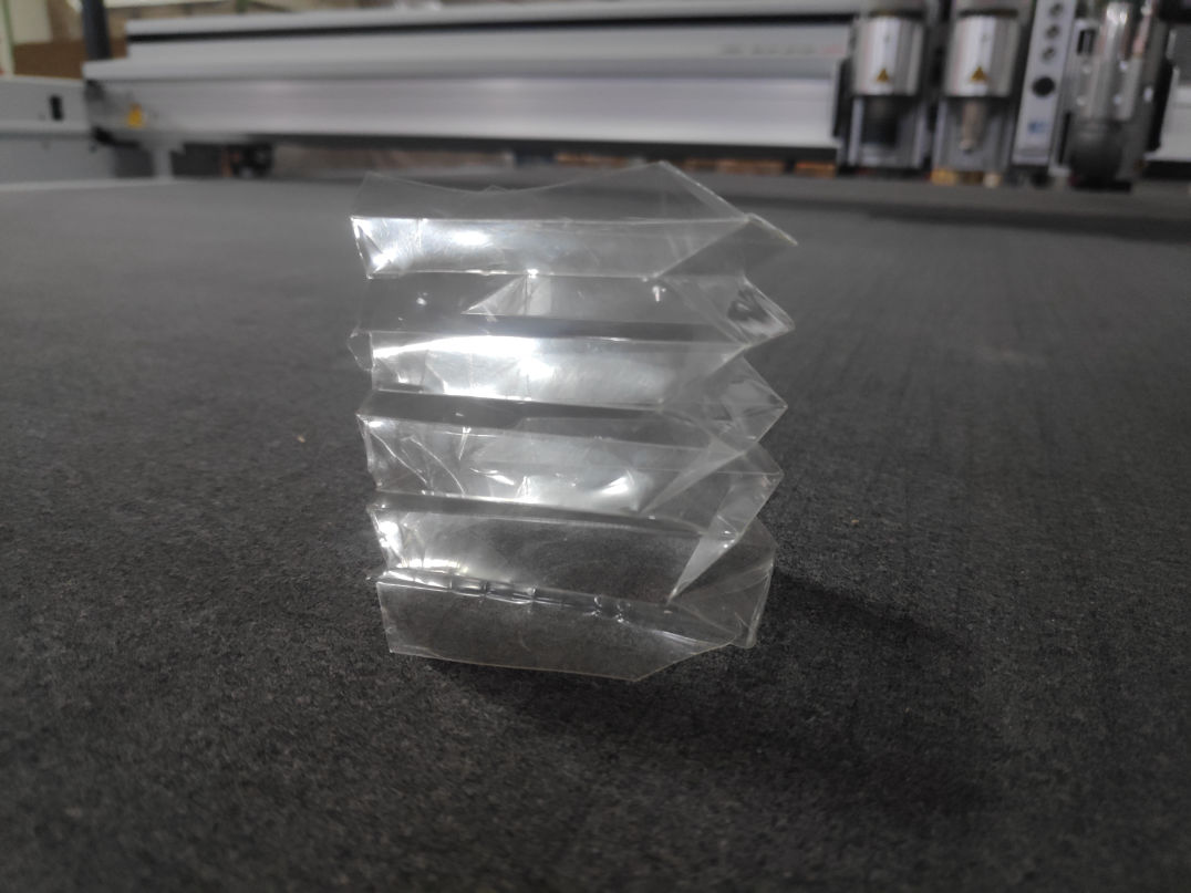
Contracted form
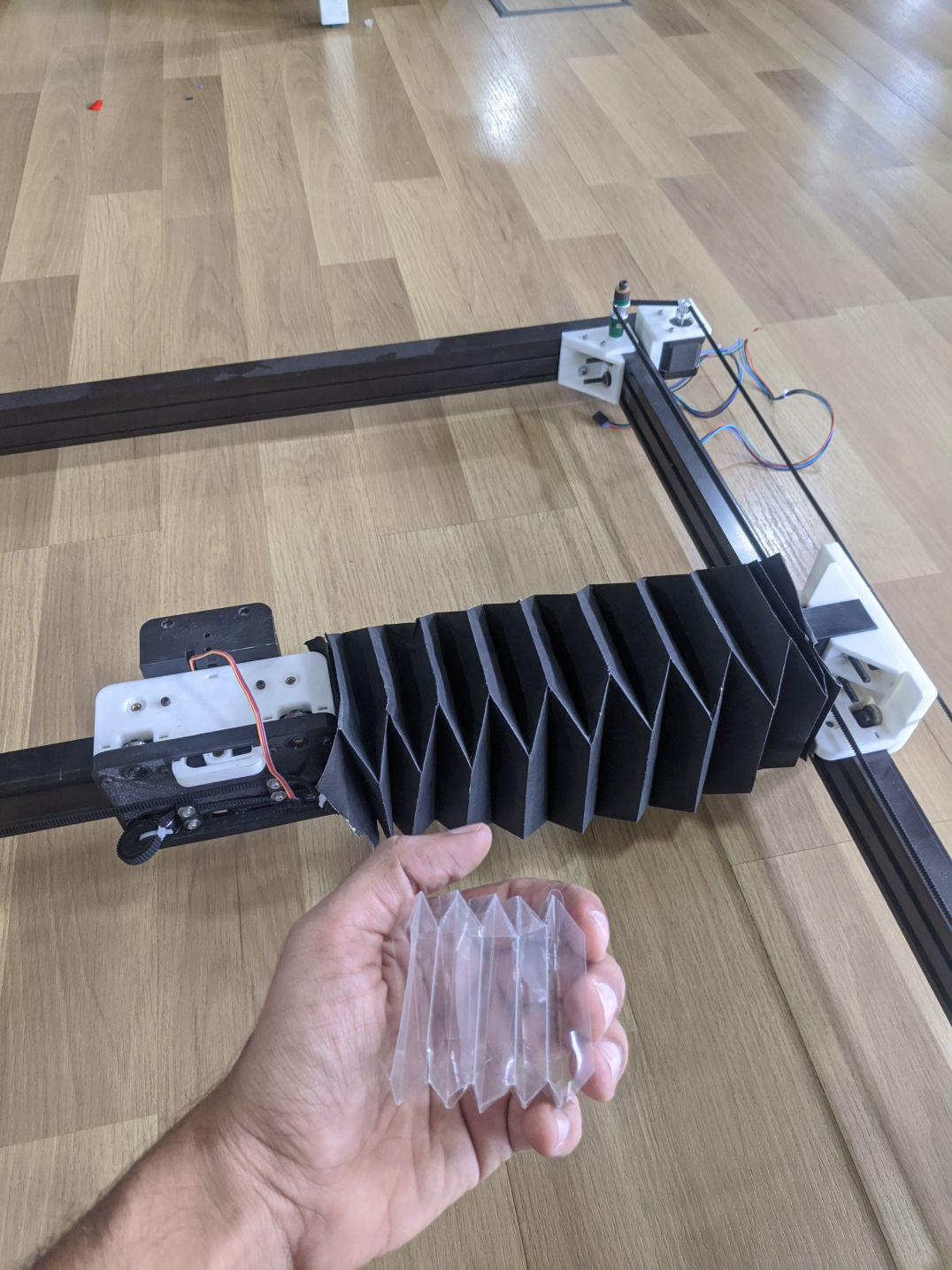
Expanded form
Short Working video
Made with Mobirise - Get now